 Español (Taducido por Google)

The ion exchange capacity is divided into cation exchange capacity (CEC) and anion exchange capacity (AEC), and denotes how much ions the packing material can retain per unit weight. For HPLC packing materials, “meq (milliequivalents)/g” and “meq/100 g” are widely used. With SI units, the ion exchange capacity is expressed in “mmol/g” or “cmol/kg”. For polymer packing materials, “meq/mL” and “meq/L” are also used.

Search
You have no items in your shopping cart.
HPLC Column Technical Guide
Chapter 1: How to Use Buffers
Table 1 shows pKa values of frequently used buffers in reversed phase HPLC. Ka stands for an acid dissociation constant and pKa is its negative logarithm. The buffer capacity becomes maximum when the pH of the buffer is its pKa.

In general, acetate buffers are prepared by mixing acetic acid and sodium acetate. However, when a volatile buffer is needed (e.g. for LC/MS(/MS)), ammonium acetate is used instead of nonvolatile sodium acetate. When an acid or a base is added to a buffer, the pH change is suppressed by a shift of the equilibrium (I) in the direction of diminishing the increase in the concentration of the added compound.
This buffering capacity is highest when the pH is within pKa±1. For example, acetate buffers have the highest buffering capacity when the pH is between 3.5 and 5.5 because the pKa of acetic acid is 4.56. In practice, buffers are prepared by adding an acid or a base to a salt solution (concentration: a few mM to a few dozen mM) of its conjugate base (e.g. sodium salt) or conjugate acid (e.g. ammonium salt).
The pKa of the analyte is another important factor. If the pH of the mobile phase is around pKa of the analyte, the reproducibility of the retention time becomes low. This is because a slight pH difference between mobile phase preparations changes the degree of dissociation of the analyte. Particularly, it is recommended to set the mobile phase pH smaller than pKa-2 or higher than pKa+2. Fore example, imidazole is a basic compound with pKa of 7.01. Therefore, most of the molecules exist as an imidazolium ion when the pH is below 5, while most of them are in their non-ionized form when the pH is above 9.

In general, the retention in reversed phase HPLC becomes low when analytes are in their ionic forms. In other words, if the pH of the mobile phase keeps the analytes in their non-ionized form, the retention becomes relatively strong. For example, imidazole is more strongly retained in the column when the pH of the mobile phase is above 9 compared to the pH below 5 where imidazole is ionized. Base-resistant columns such as InertSustain C18 enable analysis with such basic mobile phases. Ion-pair reagents are used to retain ionized compounds.
Therefore, the pH has to be adjusted such that the analytes are ionized. When analyzing imidazole with an ion-pair reagent, for example, the pH below 5 is typically employed to ionize imidazole.
Table 1. pKa values of major buffering agents.

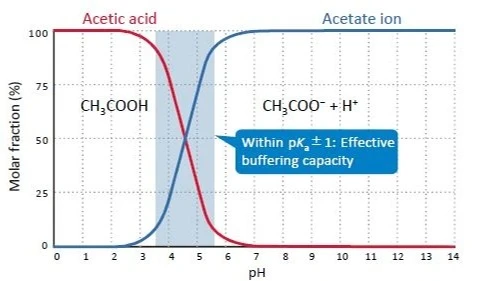
Figure 1. pH dependence of the mole fraction of acetic acids (25°C)

Figure 2. pH dependence of the mole fraction of imidazole (25°C)
Chapter 2: Organic Solvents for Mobile Phases
In Reversed Phase Mode
Changing the type of organic solvent in the mobile phase varies retention times in many cases. This is because the elution strength depends on the type of organic solvent. In order to keep the retention times constant among different organic solvents, the mobile phase composition has to be adjusted.
When there is a change in the type of organic solvent, it is recommended to perform peak identification again because the elution order might be changed. In some cases, overlapping peaks are separated by changing the type of organic solvent.

Figure 1. Comparison of the concentrations of organic solvents to yield similar elution patterns.
In HILIC Mode
Acetonitrile is by far the most commonly used organic solvent in HILIC mode. When switching the organic solvent from acetonitrile to methanol, the retention becomes too weak in practice. Alternatives to acetonitrile in HILIC mode are acetone and THF.
However, note the disadvantages of these two solvents. Acetone is unsuitable for UV detectors because of its higher UV absorption than that of acetonitrile. THF causes swelling in PEEK, which is widely used for HPLC tubing. Therefore, make sure that there are no wetting parts made of PEEK in your HPLC system when using THF.

Figure 2. Variation of retention time of melamine with change in the concentrations of organic solvents.
In Normal Phase Mode
It is common to use mixtures of hexane and ethanol for the mobile phase. However, when the retention for the target compound is too weak, the ethanol concentration has to be extremely low. In this case, 2-propanol or ethyl acetate, which is less polar solvent than ethanol, is alternatively used.
The weaker elution strength of these solvents allows for a higher concentration in the mobile phase, which makes mobile phase preparation easy and improves reproducibility.

Figure 3. Elution strength of major organic solvents.
Chapter 3: How to Replace a Non-aqueous Solvent with an Aqueous Solvent
Normal phase columns of InertSustain and Inertsil are filled with a non-aqueous solvent. When using these columns in reversed phase mode, replace the solvent by following the procedure shown in Figure 1.
Especially if the mobile phase contains a salt, please avoid salt precipitation to prevent damage to the column. 2-propanol (IPA)and ethanol are typical intermediate solvents and alcohols generate a relatively high column pressure. Please be careful of the maximum operating pressure of the column and adjust the flow rate if necessary.
Table 1. Example of the initial solvent.
| Mode | Column | Solvent |
| Normal Phase | Hexane/ethanol |
Figure 1. How to replace the mobile phase.

Figure 2. The effect of intermediate solvent.


Chapter 4: Tubing Connection
When making a connection with either stainless steel tubing or plastic tubing, the tubing has to be pushed toward the end fitting. If the tubing cannot reach the bottom of the end fitting, as shown in Figure 1, there is a dead volume left in the connection and peaks are distorted.
Plastic tubing is so soft that it has to be carefully cut to avoid a diagonal or compressed cut surface, which can make a dead volume or pressure increase. Our “clean cutter” can keep the cut surface clean.

Figure 2. Comparison of cut surfaces (0.25 mm I.D. PEEK tubing).

Figure 1. Connection examples.

Clean Cutter
| Description | Cat. No |
| Clean Cutter | 6010-81270 |
| Clean Cutter (a spare blade included) | 6010-81271 |
When a connection consists of stainless steel tubing and metal parts, it is sometimes impossible to change the positions once the they are fixed. If this tubing is connected to a column with a different end fitting type, a dead volume can be created.
Most UHPLC systems employ UP type fittings instead of Waters type fittings, which are commonly used in conventional HPLC systems. In such a case, it is convenient to use fittings compatible to any end fitting,

Figure 3. End fitting types.
Chapter 5: Supplementary Information on Units Used in HPLC
Commonly Used Units in HPLC
SI Prefixes
| Value | 10-2 | 10-3 | 10-6 | 10-9 | 10-12 | 10-15 | 10-18 |
| Prefix | centi | milli | micro | nano | pico | femto | atto |
| Symbol | c | m | μ | n | p | f | a |

Length unit conversion
| mm | inch |
| 1.00 | 0.039 |
| 1.58 | 0.062 (1/16") |
| 3.17 | 0.125 (1/8") |
| 6.35 | 0.25 (1/4") |
| 25.4 | 1.00 |
Pressure unit conversion
| Mpa | Kgf/cm2 | psi | bar |
| 0.007 | 0.07 | 1.00 | 0.07 |
| 0.098 | 1.00 | 14.0 | 0.98 |
| 1.000 | 10.2 | 145 | 10 |
Volume unit conversion (liquid)
| L | m3 | gallon (UK) | gallon (US) |
| 1.000 | 0.001 | 0.22 | 0.26 |
| 1000 | 1.000 | 220.0 | 264.2 |
| 4.55 | 0.0046 | 1.000 | 1.201 |
| 3.79 | 0.004 | 0.83 | 1.000 |
Generally used flow rate for each column I.D. (5 µm particles, in reversed phase or normal phase mode)
| I.D. (mm) | 50 | 30 | 20 | 14 | 10 | 7.6 | 6 | 4.6 | 4 | 3 | 2.1 | 1.5 | ||||||
| Flow rate (mL/min) | 110 | 40.0 | 20.0 | 9.0 | 5.0 | 3.0 | 1.7 | 1.0 | 0.8 | 0.4 | 0.2 | 0.1 | ||||||
| I.D. (mm) | 1 | 0.1 | 0.05 | |||||||||||||||
| Flow rate (µL/min) | 50.0 | 0.5 | 0.1 | Note: the optimal flow rate depends on the particle size & the separation mode. | ||||||||||||||
Volume of Tubing

Large I.D. leads to peak dispersion between the injector and the column, and between the column and the detector. However, too narrow I.D. increases the system pressure. Choose proper I.D., depending on your purpose.
What is ppm?

Chapter 6: Basic Chromatographic Terms
Retention Time
The retention time tR shows the arrival time of the peak center at the detector. It is important to confirm the reproducibility of the retention time because the peak identification in HPLC is based on tR.
Retention factor (k)
Normal-phase columns of InertSustain and Inertsil are filled with a non-aqueous solvent. When using these columns in reversed phase mode, replace the solvent by following the procedure shown in Figure 1. Especially if the mobile phase contains a salt, please avoid salt precipitation to prevent damage to the column. 2-propanol (IPA)and ethanol are typical intermediate solvents and alcohols generate a relatively high column pressure. Please be careful of the maximum operating pressure of the column and adjust the flow rate if necessary.
Resolution (Rs)
Resolution Rs describes how well two adjacent peaks are separated. In general, Rs = 1.5 is defined as baseline separation. Rs is given by the equation below with the retention factor k, the theoretical plate number N and the separation factor a:

Peak asymmetry (tailing factor)
Peak asymmetry (Asy) can be expressed as follows:
.jpeg)
- Causes of tailing (Asy > 1)
- Analyte adsorption in the column
- Dead volumes in pre- or post-column connections
- Cause of leading (fronting) (Asy < 1)
- Mass overload of the sample
- Causes of Asy >> 1 or Asy << 1 for all peaks
- Column defects
- Filter clogging


Need Help Finding The Right HPLC Column?
Leave a comment